摘要
质子交换膜燃料电池系统运行时, 会短暂存在不需要功率输出的工况. 为使系统在低功耗下零功率输出, 需要考虑控制目标多样性和动态模型复杂性的问题, 带来了阴极进气流量和电堆输出功率高精度跟踪控制的挑战. 面向系统怠速控制, 本文构建了一种基于模型的非线性控制框架. 首先, 推导了输出功率与阴极进气流量的非线性动态模型; 其次, 设计了非线性扩展卡尔曼滤波观测器和状态反馈控制器相结合的控制方案; 最后, 在质子交换膜燃料电池实验平台上进行控制方案验证, 并与比例–积分–微分(PID)控制器进行对比实验. 实验结果表明, 本文中所提出的控制策略, 可以实现燃料电池系统的怠速控制, 达到系统零功率输出的目的, 且较PID控制器具有更快的响应速度和更好的系统动态.
关键词
Abstract
When the proton exchange membrane fuel cell (PEMFC) system is running, there will be a condition that does not require power output for a short time. In order to achieve zero power output under low power consumption, it is necessary to consider the diversity of control targets and the complexity of dynamic models, which brings the challenge of high-precision tracking control of the stack output power and cathode intake flow. For system idle speed control, a modelbased nonlinear control framework is constructed in this paper. Firstly, the nonlinear dynamic model of output power and cathode intake flow is derived. Secondly, a control scheme combining nonlinear extended Kalman filter observer and state feedback controller is designed. Finally, the control scheme is verified on the PEMFC experimental platform and compared with the proportion-integration-differentiation (PID) controller. The experimental results show that the control strategy proposed in this paper can realize the idle speed control of the fuel cell system and achieve the purpose of zero power output. Compared with PID controller, it has faster response speed and better system dynamics.
1 Introduction
Limited by environmental pollution and the shortage of fossil energy, new energy technology has gradually become a research hotspot at present. As an important branch of new energy technology, hydrogen energy is considered to be the most potential alternative energy. Proton exchange membrane fuel cell (PEMFC) can convert hydrogen energy into electricity, which has the advantages of low operating temperature, high power density and high efficiency. It has bright development prospects in the field of transportation and electric power [1-4] .
The PEMFC system is combined with the vehicle power battery in the field of transportation. Through the energy management system, the output power is adjusted to realize the response to the demand power in the process of vehicle driving [5-7] . However, for the fuel cell stack, frequent power switching and high output voltage will cause the attenuation of its service life [8-9] . In some studies, the health state constraint of fuel cell is added to the energy management control algorithm to optimize the service life of the fuel cell system (FCS) by inhibiting frequent changes in the power demand of the system. Reference [10] proposed an energy management strategy (EMS) based on fast reinforcement learning. Based on the pre-initialization framework, rapid convergence to the optimal result reduces fluctuations in the output of the FCS and helps to improve the service life. Reference [11] proposed an EMS based on deep reinforcement learning (DRL) to consider and evaluate the durability of fuel cells with the degradation model. The action space of the DRL algorithm is limited by the efficiency characteristics of fuel cells to improve fuel economy. Reference [12] proposed a degenerate adaptive EMS, the polarization curves and fuel cell efficiency models of the FCS under different health states were established. Dynamically adjust power distribution between FCS and batteries during degradation to improve the fuel economy.
In the above research, the fluctuation of fuel cell output is suppressed by the EMS to regulate the demand energy, so as to extend the service life of the system. However, when the FCS is working, there will still be a condition of zero power demand for a short period of time. This study will focus on the control strategy when the FCS receives short zero output during normal operation. At present, the control command of zero output is realized by stopping in the actual system. The scheme will have a short period of downtime and restart working mode. During shutdown, it is necessary to purge the exhaust gas and release all the remaining energy in the reactor, which will cause power loss and increase the amount of hydrogen consumption. When the system is restarted, the battery is required to supply power to the auxiliary devices of the system, which will cause fluctuations in the power demand of the power battery. When the system is shut down or restarted, it will not be able to respond to the required power in a timely manner, resulting in a temporary failure of the EMS. Therefore, the FCS to achieve zero power output through a short shutdown, resulting in increased hydrogen consumption, increased parasitic power and reduced stack life, which is not an optimal control strategy. It is necessary to explore an idle control scheme that can make the FCS run at zero output. This can not only effectively mitigate the impact of frequent start-stop on the stack life, but also respond to the power demand of the EMSwhen the system is running at idle speed.
In order to realize the idle operation of the FCS, the output of the stack needs to be calculated precisely according to the electrochemical reaction principle of the fuel cell. The output power is completely consumed by the auxiliary devices. A number of research efforts have been undertaken to model the output characteristics of fuel cells: Reference [13] estimated the steady-state battery voltage distribution of a60 kW 140 batteries stack based on an artificial neural network model, but the dynamic characteristics of the stack at work were not considered. The output dynamics of PEMFC are described by fractional order state space equation in references [14-15] . The dynamic processes of PEMFC are tracked by fuzzy genetic algorithm and particle swarm optimization genetic algorithm, respectively. Reference [16] put forward a semi-empirical dynamic model of output voltage based on experimental data, which can predict the transient response of voltage when current step change. In reference [17], researchers established an organic gray backpropagation neural network model for output voltage to predict PEMFC voltage during start-stop operation, and elaborated that the stack voltage during start-stop is closely related to current, hydrogen pressure and temperature. These researchers used semi-empirical models to describe the output voltage dynamics, ignoring the chemical reaction process. Based on the law of conservation of mass and Nernst equation, researchers in references [18-20] established an open-circuit voltage dynamic model of FCS, taking into account the voltage difference caused by activation, ohmic and concentration loss, so that the model is closer to the real electrochemical reaction.
When the FCS is working, there will be a temporary condition that does not require output. If the response is performed only by stopping, the hydrogen consumption will increase, the parasitic power will increase, and the life of the stack will decrease. The idle speed control of FCS is proposed for short time zero output condition. In this paper, the idle operation is realized by making the output offset the required power of the auxiliary devices. During the operation, the hydrogen flow rate is regulated by the hydrogen circulating pump to ensure an adequate supply of hydrogen. The cathode side absorbs air through the air compressor. The cathode intake flow rate is adjusted by the air compressor. However, the speed of the air compressor is not only closely related to the intake volume, but also affects the required power of the auxiliary devices. The collaborative control of intake flow and output power brings about the problem of control target diversity. In addition, the output power is modeled by the mass conservation law and Nernst equation. In the model, there are obvious coupling and nonlinear characteristics between output and intake flow, which brings about the complexity of dy-namic model. Therefore, how to achieve high precision tracking control of cathode intake flow and stack output are the two control challenges existing in idle operation.
Aiming at the problem of idle speed control, a nonlinear dynamic characteristic model of control-oriented output and cathode intake flow is established. A modelbased control framework for nonlinear system is proposed. The idling control of FCS is realized through the control scheme of extended Kalman filter observer (EKFO) and state feedback controller. The scheme is verified on PEMFC experimental platform and compared with PID, which proves the effectiveness of the proposed control scheme.
The three innovations of this paper are as follows:
a) A nonlinear model including the output and the intake flow of the cathode is established, and the model is verified on the PEMFC experimental platform.
b) A model-based nonlinear control framework is proposed, which combines observer and controller to control FCS idle operation. Modeling error and external disturbance error were observed by EKFO. The error is compensated to the state feedback controller.
c) The effectiveness of the scheme is verified on PEMFC experimental platform and compared with PID. The proposed control scheme can be deployed in the actual system, and the idle speed control can be realized under various conditions. Compared with PID, it has faster response speed and better system dynamics.
The rest of this paper is organized as follows. The modeling is described in Section 2. In Section 3, the derivation of the control scheme is introduced. In Section 4, the experimental results are analyzed. Finally, the main conclusions are summarized in Section 5.
2 Model description
The idle speed of the FCS is to make its net output power of zero kilowatt (kW) , and the idle speed of the FCS can be achieved by making the output power of the fuel cell stack equal to the current power demand of the auxiliary devices, such as air compressor, highpressure water pump and hydrogen circulation pump. At present, the net output can reach hundreds of kilowatts, and the power consumed by the auxiliary devices is less than 1 kW, which is far less than the output of the FCS. Therefore, in order to achieve idle operation of the system, the gas supply pressure between the cathode and the anode is maintained near the atmospheric pressure, so that the stack works in the low load area. Since the gas at the anode end is high-purity hydrogen, the unused hydrogen will still be recycled on the anode side, so there is no need to consider the dynamics of hydrogen when the system is running at idle speed. The cathode side is the air input through the air compressor, the fuel cell reaction consumes the oxygen in the air, the remaining waste gas in the air is directly discharged without recycling. At the same time, by adjusting theload current of the FCS, the output is adjusted, so that the output can just offset the demand power of the auxiliary devices. Therefore, a nonlinear dynamic characteristic model of stack output and cathode flow rate is established to provide a theoretical basis for the design of subsequent control schemes.
2.1 Fuel cell stack output voltage model
The energy released during the chemical reaction can be described by the Gibbs free energy [18-20]. The open circuit voltage of a single fuel cell (E) is described by means of Nernst voltage,
(1)
where TFC denotes the operating temperature, and represent the partial pressure of hydrogen and oxygen, respectively. The actual output voltage is less than the open circuit voltage described in Eq. (1) . The main reason for the difference is caused by the internal loss and the irreversibility after operation. The terminal voltage of a fuel cell stack (UFC) can be described as
(2)
where ncell denotes the number of fuel cells in the stack, Vact, VΩ, Vconc respectively correspond to the pressure drop caused by activation loss, ohmic loss, and concentration loss. The dynamic characteristics of the terminal voltage can be described as
(3)
2.2 Cathode pressure model
The fuel cell stack is composed of multiple fuel cells, and the partial pressure of oxygen cannot be measured directly by the sensor. The dynamic characteristics of cathode pressure and oxygen partial pressure established in reference [20] are simplified and numerically derived. The pressure dynamics are described as
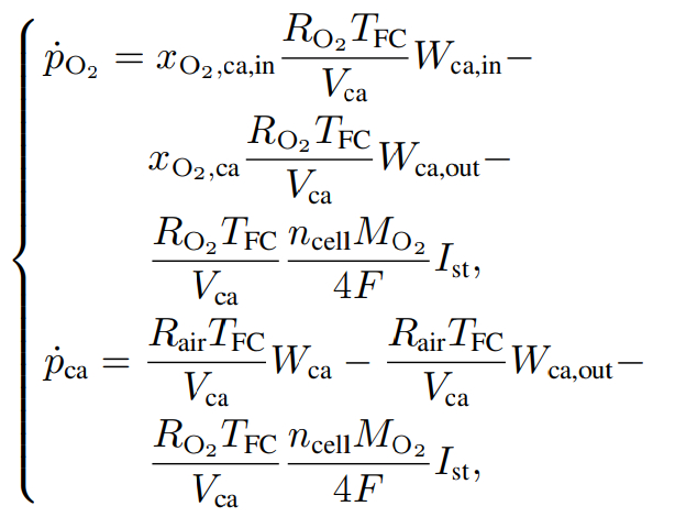
(4)
where Rair and represent the gas constant of air and oxygen respectively, represents the molar mass of oxygen, pca denotes the cathode pressure, Vca rep-resents the volume of the cathode intake manifold, F denotes the Faraday constant, Wca and Wca, out represent the cathode flow and exhaust flow rate, respectively, Ist denotes the load current of the fuel cell stack, and denote correspond to the oxygen mass fraction of the intake air and the oxygen in the reactor, respectively, where the value is
(5)
Considering the idle speed control, the cathode pressure is near the atmospheric pressure, so the pressure dynamic is ignored, and the cathode oxygen partial pressure is
(6)
2.3 Cathode flow rate model
In this paper, screw air compressor is selected, and the flow rate has a linear relationship with the speed of the air compressor,
(7)
where Ncp denotes the air compressor speed, kc and bc are the linear coefficient of the air compressor speed and the intake flow rate, which can be fitted by the measured data of the test bench. Considering the delay between the air compressor speed and the control command, the air compressor speed dynamic is established,
(8)
where Tcp denotes the air compressor response time, Ncmd denotes the air compressor speed control command. The dynamic of the output voltage of the fuel cell stack is described by Eqs. (3) – (6) as follows [20] :
(9)
Combined with the dynamic characteristics of the output voltage of the fuel cell stack, the nonlinear dynamic characteristics of the output power of the stack and the cathode flow rate are described as follows:
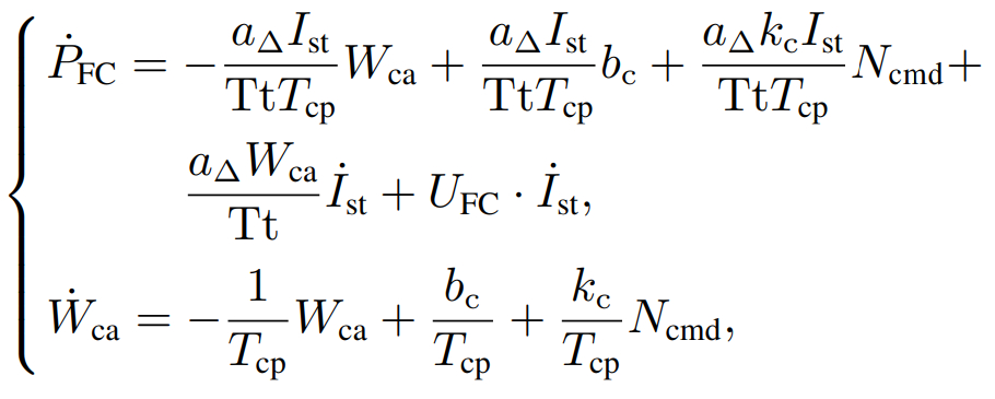
(10)
where a∆ and Tt are the intermediate variables
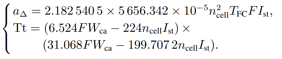
(11)
Thus, a nonlinear dynamic model of the output and cathode intake flow is established.
3 Controller design
Based on the established nonlinear model of output and cathode intake flow. An idling control scheme of PEMFC system based on EKFO and state feedback controller is designed. The error of the nonlinear dynamic characteristic model is predicted by EKFO, and the modeling error is compensated into the model. The state feedback controller is used for the cooperative control of the output and the intake flow. The reference value of the state variable is obtained through the offline map table of the load current and the power consumedby the auxiliary devices. The control block diagram of the scheme is shown in Fig.1.
3.1 Extended Kalman filter observer
Some assumptions are made in the modeling of the output power and flow rate of the fuel cell stack, which will cause the deviation between the model and the actual system. In order to eliminate the deviation part of the model, a nonlinear observer based on EKFO is designed to estimate the system deviation and compensate the estimated deviation to the controller, so as to obtain better control effect.
Kalman filter is based on optimization and recursion. According to the coefficient matrix of linear system, Kalman filter performs two steps of time and measurement update, so the state estimation of linear system is realized. The extended Kalman filter is a state estimation method for nonlinear systems. Compared with the linear method, the calculation process of iterative Jacobian matrix is increased, and the calculation amount is more complicated. First, the modeling error is introduced into Eq. (10) , and the observed variable is described as
(12)
where x represents the state quantity, d represents the modeling error, u represents the amount of control, z represents the observed quantity, the lower corner mark k and k − 1 represent the state value of its current moment and the previous moment, respectively.

Fig.1System controller
Time update
The prior state estimation and the prior state estimation error covariance matrix are described as
(13)
where Ak and Wk are the time updated Jacobian matrix, can be described as
(14)
Measurement update
The Kalman gain Kk, posterior state estimation and posterior state estimation error covariance matrix Pk are described as
(15)
where Hk and Vk are the measuring updated Jacobian matrix, it can be described as
(16)
3.2 State feedback controller
The modeling error estimated by the EKFO is compensated to the dynamic model of output power and intake flow. A standard state feedback controller based on nonlinear model is designed and the control rate is derived. The state variables and control quantities of the idle speed control system are as follows:
(17)
The dynamic model after modeling deviation compensation is described as
(18)
Construct an error model, describing the error as the difference between the reference value and the actual value of the state variables
(19)
The corner mark ‘ref’ in the formula represents the reference value of the state variables, and the dynamic control error can be expressed as
(20)
Build a state feedback controller
(21)
The system control input is derived as
(22)
4 Experimental result
In order to verify the feasibility of the idling control scheme of FCS based on EKFO and state feedback controller, the experimental verification and analysis of the control scheme are carried out on the experimental platform. The experimental platform is shown inFig.2. The experimental platform includes PowerCell36 kW fuel cell stack, air supply subsystem, hydrogen supply subsystem, hydrothermal management system and energy management system, which can completely simulate the real operating state. The experimental platform uses dSPACE as the controller. The control scheme was compiled by MATLAB/Simulink, downloaded to the controller through optical fiber communication, through Control Desk to realize online control. During the experiment, the FCS idle speed control is realized by querying the speed-consumption power map of auxiliary devices such as air compressor, high pressure water pump and hydrogen circulation pump to obtain the consumption power of auxiliary devices.

Fig.2PEMFC experimental platform
4.1 Model verification
By collecting the real data of state variables and the observed value of EKFO, the authenticity of the reactor output power and intake flow model established in Section 2 is verified. Step change conditions for output power and intake flow are designed to verify the model. The experimental data are shown in Fig.3.

Fig.3Model verification
Figure3 (a) – (b) respectively correspond to the step change of output power and intake flow. In Fig.3, theobserved value of EKFO can track the real data, and both of them maintain the same change trend. Therefore, the model established in Section 2 can represent the dynamic characteristics of the system.
4.2 Experimental result
In the experiment, the unit of flow rate is set as grams per second, the unit of load current, output voltage and output power are ampere, volt, and watt, respectively. The speed of air compressor, hydrogen circulating pump and water pump is thousand revolutions per minute (kr/min−1 ) . Since the air compressor speed is defined as the control quantity in the controller design, the air compressor speed will be dynamically adjusted according to the control rate, so three working conditions are selected to verify the idle speed control effect of the FCS, respectively are: Verify the idling control effect under steady state operation of the FCS, verify the idling control effect on step change of pump speed and verify the idling control effect on step change of hydrogen circulating pump speed.
Condition 1 Steady state.
In order to verify the control effect of idle speed control in steady state of FCS. The first working condition fixed the speed of the high pressure pump and the hydrogen circulating pump to verify the control effect.
The speed of auxiliary devices and system controlquantity are shown in Fig.4. Figure4 (a) is the speed of auxiliary devices. The speed of air compressor fluctuates with the control quantity, the speed of water pump is fixed at 3.5 kr/min−1, and the speed of hydrogen circulating pump is fixed at 2.5 kr/min−1 . The output and cathode inlet flow control effect of fuel cell stack are shown in Fig.5. The observer designed in this paper can fit the state variable reality well, which indicates that the EKFO designed in the previous paper has a good observation effect on the state variable and modeling deviation. At the same time, the state variable can better track the real value, which can show the effectiveness of the state feedback controller designed in this paper. As can be seen from the output curve of the stack in Fig.5 (a) , the real output of the stack fluctuates around the reference value, and its fluctuation range is about ±50 W.

Fig.4Condition 1: Auxiliary devices speed and control law

Fig.5Condition 1: State variable value
The load current, output voltage and net output are shown in Fig.6. The load current and output voltage of the stack are collected by DC-DC converter. Limitedby the sampling accuracy, the current and voltage values will fluctuate, which will lead to fluctuations in the output. The fuel cell loaded in the experimental platform consists of 264 fuel cell units with a rated power of 36 kW. As can be seen from the net output of the FCS in Fig.6 (c) , based on the proposed control scheme, the net output power of the system can be stabilized at 0 W, the error range is about ±50 W, and the control accuracy can reach 0.1%.

Fig.6Condition 1: Output power
Condition 2 Step change of water pump speed.
When the fuel cell generates energy, it will also be accompanied by heat generation. It is necessary to adjust the temperature of the reactor by changing the speed of the high-pressure water pump. In the second working condition, the hydrogen circulating pump is fixed and the pump speed is set as a step change to verify the idle speed control effect.
The speed of auxiliary devices and the amount of system control are shown in Fig.7. Figure7 (a) shows the speed of the auxiliary device, wherein the speed of the air compressor fluctuates with the control quantity, the speed of the hydrogen circulating pump is fixed at 1.5 kr·min−1, and the speed of the water pump is set as a step change. The output and cathode inlet flow control effect are shown in Fig.8. The actual value, observed value and reference value of state quantity have good tracking effect. The load current, output voltage of the fuel cell stack and the net output power of the FCS are shown in Fig.9. The output power of the system is around 0 W, but when the pump speed changes step by step, the output power will overshoot.

Fig.7Condition 2: Auxiliary devices speed and control law

Fig.8Condition 2: State variable value
Condition 3 Step change of hydrogen circulating pump speed.
The hydrogen supply system may have too small hydrogen flow at atmospheric pressure, resulting in a shortage of hydrogen. The hydrogen flow rate will be adjusted by controlling the speed of the hydrogen circulating pump. In the third working condition, the speed of the pump is fixed, and the speed of the hydrogen circulating pump is set as a step change to verify the idle speed control effect at this time.


Fig.9Condition 2: Output power
In particular, as shown in Fig.7 (a) and Fig.8 (b) , when the pump speed changes step by step, due to the increase in the demand power of the pump, the corresponding intake flow rate should also increase, so that the speed of the air compressor also increases at the same time, resulting in the phenomenon that the speed of the air compressor and the speed of the pump increase at the same time. Conversely, the two synchronously step down.
The speed of auxiliary devices and system control quantity are shown in Fig.10. The speed of the air compressor fluctuates with the control quantity, the speed of the water pump is fixed at 3 kr/min−1, and the speed of the hydrogen circulating pump is set as a step change. From the speed curve of the hydrogen circulating pump, it can be seen that the speed will overshoot when the speed is adjusted by the step transformation, which is caused by the controller characteristics of the hydrogen circulating pump. The output power and cathode inlet flow control effect of fuel cell stack are shown in Fig.11. The load current, output voltage of the fuel cell stack and the net output power of the FCS are shown in Fig.12.
In particular, the power consumption of the highpressure pump used in the PEMFC experimental platform is higher than that of the hydrogen circulating pump. As shown in Fig.9 (a) and Fig.10 (b) , when the speed of the hydrogen circulating pump changes step by step, the intake flow rate and the speed curve of the air compressor do not change step by step as in the second condition. This is due to the small change in energy consumption required by the step change in the speed of the hydrogen circulating pump.
4.3 Comparative experimental results
The control scheme of EKFO combined with state feedback controller is compared with the control effect of PID controller. As can be seen from the second group of experimental conditions in Section 4.3, when the pump speed is adjusted by step transformation, the expected output power will change greatly, which canbetter demonstrate the dynamic characteristics between the two control schemes. Therefore, the hydrogen circulating pump speed is fixed at 2.5 kr/min−1 and the pump speed is set as a step change.

Fig.10Condition 3: Auxiliary devices speed and control law

Fig.11Condition 3: State variable value


Fig.12Condition 3: Output power
The speed of air compressor, water pump and hydrogen circulating pump corresponding to the two control schemes are shown in Fig.13, and the control effect corresponding to the two control schemes are shown in Fig.14. The application of PID control algorithm, the real value of the output power needs a long adjustment time to track the expected value, and the corresponding air compressor speed will be adjusted for a longer time to be stable. Compared with this, the proposed control scheme has a faster response speed, the real value of the output power can be changed with the reference value, and has better system dynamics.

Fig.13Contrast experiment: Auxiliary devices speed


Fig.14Contrast experiment: Experimental result
5 Conclusion
Aiming at the idle speed control of PEMFC system, a model-based nonlinear control framework is constructed, and a control scheme based on EKFO and state feedback controller is designed. Firstly, the nonlinear dynamic model of output power and cathode inlet flow of PEMFC stack is established. Secondly, an EKFO is designed to estimate the modeling error of the nonlinear dynamic model, and the estimated error is compensated into the model. The idle speed control for FCS is realized by using state feedback controller. Finally, the designed control scheme is verified on the PEMFC experimental platform and compared with PID controller. The experimental results show that the proposed control scheme can realize the idle speed control of the FCS under various working conditions. The net output power of the system is stable at 0 W, the power error range is about ±50 W, and the control accuracy can reach 0.1%. Compared with PID controller, it has faster response speed and better system dynamics.